Injection Molding Process and Hot Runner Systems
Processing injection molds used to be considered a black art. Then came along scientific molding that decoupled fill (cavity is filled 98% with injection speed), pack (finish filling and apply pressures), and hold (allow the part to cool). Processing engineers control four plastic variables: Temperature/Heat, Flow, Pressure, and Time/Cooling. There are two details we want to point out that help shape our viewpoint on processing.
Melt Flow Index
First, most people think the term “Melt Flow Index” represents viscosity (resistance to flow). It is measured in grams per 10 min within a comparison test to other resins. It is a molecular weight, not viscosity, just a reference point. Plastic also does not follow Newton’s law of viscosity. It’s a non-Newtonian fluid, so its viscosity (resistance to flow) can change under different temperatures, injection speeds, and pressures. Ensuring consistent melt preparation (plasticizing) is the foundation of an injection molding process.
Factors like drying, total residence time (from initial screw contact to filling of the cavity), screw/barrel design and wear, precise check-ring function, machine nozzle design, and of course, the hot runner design all contribute to getting the melt to the cavity in proper condition and consistently from shot-to-shot.
Hot Runner Thermocouples
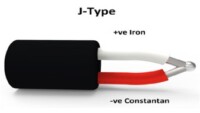
Second, a thermocouple reading is a reference point, NOT the melt temperature. The temperature reading is highly dependent on the location of the thermocouple junction. It should be at a point of stable heat loss. You should also know that type-J thermocouples (most common in injection molding) have a +/- .75% accuracy. That is about 3.75 degrees for a 500-degree zone! So, all of the marketing garbage about the temperature accuracy of controllers needs to be better understood.
When someone sets the zone setpoint on a hot runner controller, and that controller takes a reading and throws power at the zone without consideration of the other zones or the heat gain/loss trend of the tool, it will cause a lot of volatility across all zones in the system. The display can say it’s holding that 500-degree setpoint right on. Meanwhile, the on/off power spikes wreak havoc on your process, and the actual melt temperature is not even 500 degrees.
So, when you consider that two of the four plastic variables, flow and temperature, are just reference points and not absolute settings, it gives a clue to the key to injection molding process control – KEY: KEEP PLASTIC VARIABLES CONSISTENT!
Hot Runner Temperature Control
Regarding hot runner temperature control, it’s not the absolute temperature set point that matters. It’s the consistency of temperature that matters. We’ve published articles and posts about the injection molding process many times. Here are two strong references with bullet point summaries that provide insight into what is happening behind the scenes in a hot runner system.
Hot Runner Temperature Control : A Low-Investment Solution for Challenging Molding
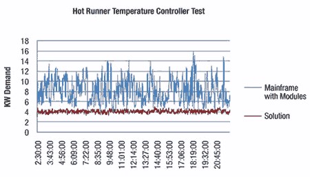
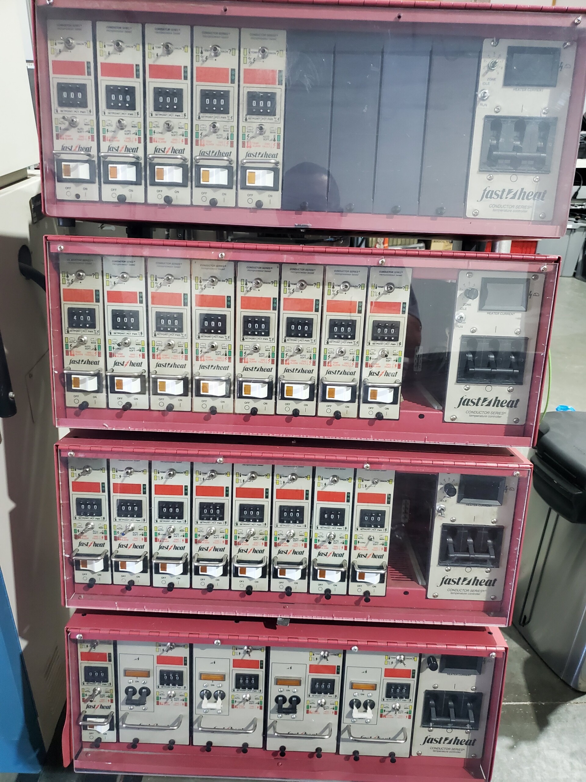
- “Rack-style” mainframes with independent modular controllers cause process volatility due to over/undershooting a zone’s temperature setpoint and the impact that has on other zones within the hot runner system. The graph to the left shows this volatility as spikes in kW demand. They also use more electricity, drive high peak kW demand costs, and contribute to planting loading challenges.
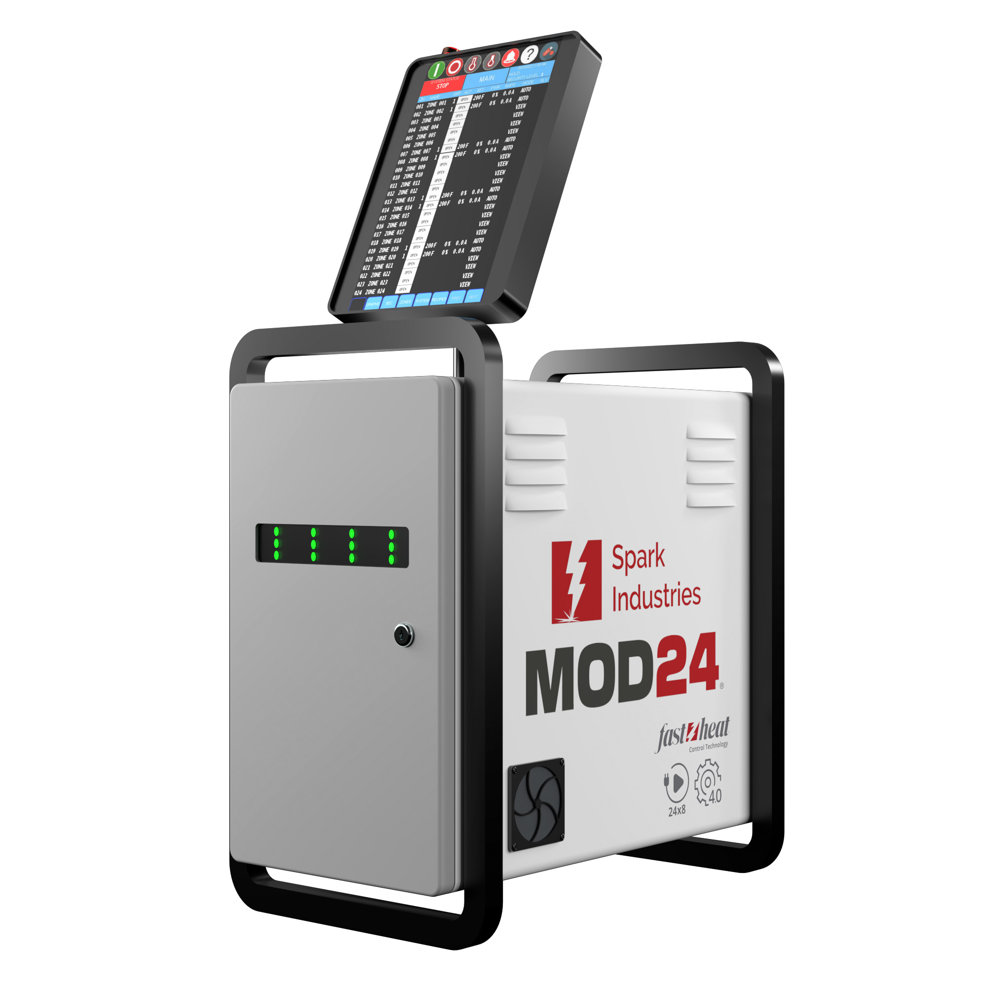
- “Smart Controllers” provide trend intelligence for all hot runner zones within a system, stabilizing the injection molding process and enabling lower operating temperatures and cavity-to-cavity balance.
- The Fast Heat Pulse Controller measures the temperature of a zone many times before calculating a % power requirement that achieves the target set point for that particular zone while also predicting the impact it will have on other zones!
Plastic Variables
It is essential to consider that the four plastic variables (temperature/heat, flow, pressure, and time/cooling) are all affected by the hot runner design of heaters, thermocouple locations, flow channels, gate details, water channels, manifold heat gain/loss, and plates.
-
- Flow channels crossing perpendicularly underneath a tubular heater will cause burning.
- Manifold thermocouples directly opposite each other will provide false feedback.
- Thermocouples should be at points of the most stable heat loss.
- Thermal balancing with proper water channel size and location will stabilize the injection molding process.
Moldflow Analysis
Hot Runner Control Impact on Moldflow Analysis
Temperature control across all zones as a unified system significantly affects the injection molding process, but other considerations exist.
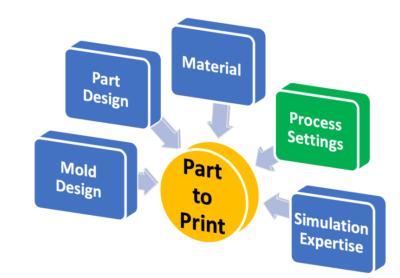
According to CAE Services, a prominent Moldflow software and analysis provider, there are five contributors to “part-to-print” success. They are:
- Mold Design
- Part Design
- Material (impacted by hot runner control)
- Process Settings (affected by hot runner control)
- Simulation Expertise
Reference: Hot Runner Troubleshooting