Hot Runner Troubleshooting
First, Staying Out of Trouble
MoldMaking Technology® and Plastics Technology magazines published articles about hot runner troubleshooting that included the importance of proper hot runner system startup. While this blog is about troubleshooting, it is fair to say that the best way to get out of trouble is to stay out of trouble. Proper start-up prevents the tool from leaking plastic. Further, it does this while minimizing hot runner system wear and downtime. And, as previously shown in our post about kW demand, it saves on peak demand kW costs. It also helps to balance shop loading of amperage.
- The Ins and Out of Hot Runner Temperature Control, MoldMaking Technology, 11/8/2021 by yours truly, Chad Root and Manny Diaz, Fast Heat by Spark Industries
- How to Detect and Prevent Hot-Runner Manifold Leaks, Plastics Technology, 8/1/2022 by Steve Johnson, MoldTrax
Four Keys to Start-Up
- Heaters absorb moisture when not in use. This moisture can cause a ground shortage if the heater is 100% after sitting for a while. Always use small amounts of power to slowly “bake” out this moisture. Do this before giving it 100% power. This will protect your heater and the thermocouple.
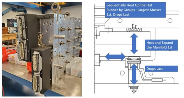
- The components in a hot runner system expand when heated. The systems start with a “cold clearance” to allow for this expansion. Expansion pressure must seal these clearances before injection or the system will leak. To properly seal this clearance without wear at the gates or between the manifold and drops, it is crucial to expand the manifolds first and nozzles (drops) last.
- Just because a component reaches setpoint temperature does NOT mean it is fully expanded enough to seal those clearances. Measuring your components at room and operating temp while recording the time it takes to achieve full expansion is how you determine the proper “Soak Time” for your hot runner system.
- Detecting leaks is a hot topic. Most leaks will occur between the manifold and the nozzle due to a lack of soak time. If starting a system for the first time, you should calculate how many shots it will take to fill the hot runner system. After that, if your cavities are not filling, the plastic is going somewhere. A % power alarm will help bring awareness to this. The leaking zone will require more power than usual to maintain the setpoint temperature. However, that may be too late. A low-temperature alarm may also be an indicator. Leaks can also occur at worn gates (due to improper sequencing over time). These types of leaks are easier to detect early on with the controller alarms. The lesson learned? Don’t cold shoot a tool!
Hot Runner Control Alarms
Before we start with alarms, it’s always best to perform preventative maintenance. See our maintenance guide for reference. Ensure there are no missing or loose grounds, out-of-spec heaters and thermocouples, direct shorts, miswires, and bent or pushed-back pins. We recommend using our MoldXChecker® and CableXChecker® .
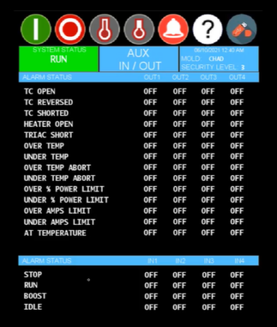
There are four main categories of alarms on our Pulse hot runner controller:
- Thermocouples [TC OPEN, TC REVERSE, TC SHORT]
- Power (Heaters) [OVER/UNDER % POWER, HEATER OPEN, TRIAC SHORT]
- Temperature [OVER/UNDER TEMP (ALARM AND ABORT)]
- Amperage [OVER/UNDER AMPS]
What do these alarms mean, and what can you do about them?
TC OPEN – The TC circuit is open. The TC circuit includes many connection points: the mold box, cable (both ends), and the controller. To keep production going, use Auto-Slave or Manual-Slave on the controller. To run this zone off of another zone’s TC, you can run the zone in Manual Mode (manual % power). The Pulse hot runner controller has ATP™ (Active Thermocouple Protection) to protect TCs from ground leakage.
TC REVERSE – A Type J TC has a white wire (+) and a red wire (-). Any of the connection points mentioned earlier could be reversed. To keep production going, use slaving or manual mode.
TC SHORT – Positive (white wire) could be shorted to ground, Negative (red wire) could be shorted to ground, or Positive and Negative could be shorted together somewhere along the circuit. This alarm occurs after the controller has established temperature readings and then detects a drastic reduction. TC wires are likely grounded in the mold or mold box, or there is a pinch in the TC. To keep production going, use slaving or manual mode.
OVER/UNDER % POWER – Set this production range to the outer range of normal operating conditions. Examples might be improper temperature settings at the sprue or in the manifold that require more % power at the nozzles. OR, a leak around the nozzle gate or in the manifold-to-nozzle mating surface, high or low melt temp, faster or slower injection speeds, or water temp being too high or low.
HEATER OPEN – There is an open in the heater, a wire, an input fuse, an output fuse, or any connection point within the heater circuit for that zone (mold box, both ends of the cables, controller). Check the connection points and fuses first. If those are good, ohm the heater. We recommend tracking ohm readings during preventative maintenance. You can then detect and replace a heater if it is near failure before putting the tool into production. Refer to MoldTrax.
TRIAC SHORT – This alarm indicates that the power module triac (on/off switch) is shorted in the closed position. This alarm automatically turns the zone off. Ensure the heater is not cross-wired to another zone (most likely in the mold box, but it could also be the cable or controller connectors). Also, check for a direct short in the hot half. We recommend using the MoldXChecker® for this test.
OVER/UNDER TEMP – This production range is set to an over/under alarm and abort range on the controller. The range and alarm type will depend on how well you know the tool’s operating condition. TC location, cooling circuits, injection speed, shear heat, etc., all affect normal operating conditions.
OVER/UNDER AMPS – This range is set to a heater-specified amperage with normal voltage conditions. Significant voltage swings or loss of heater resistance could trigger this alarm.
Situational Awareness – “Let me see what’s going on here.”
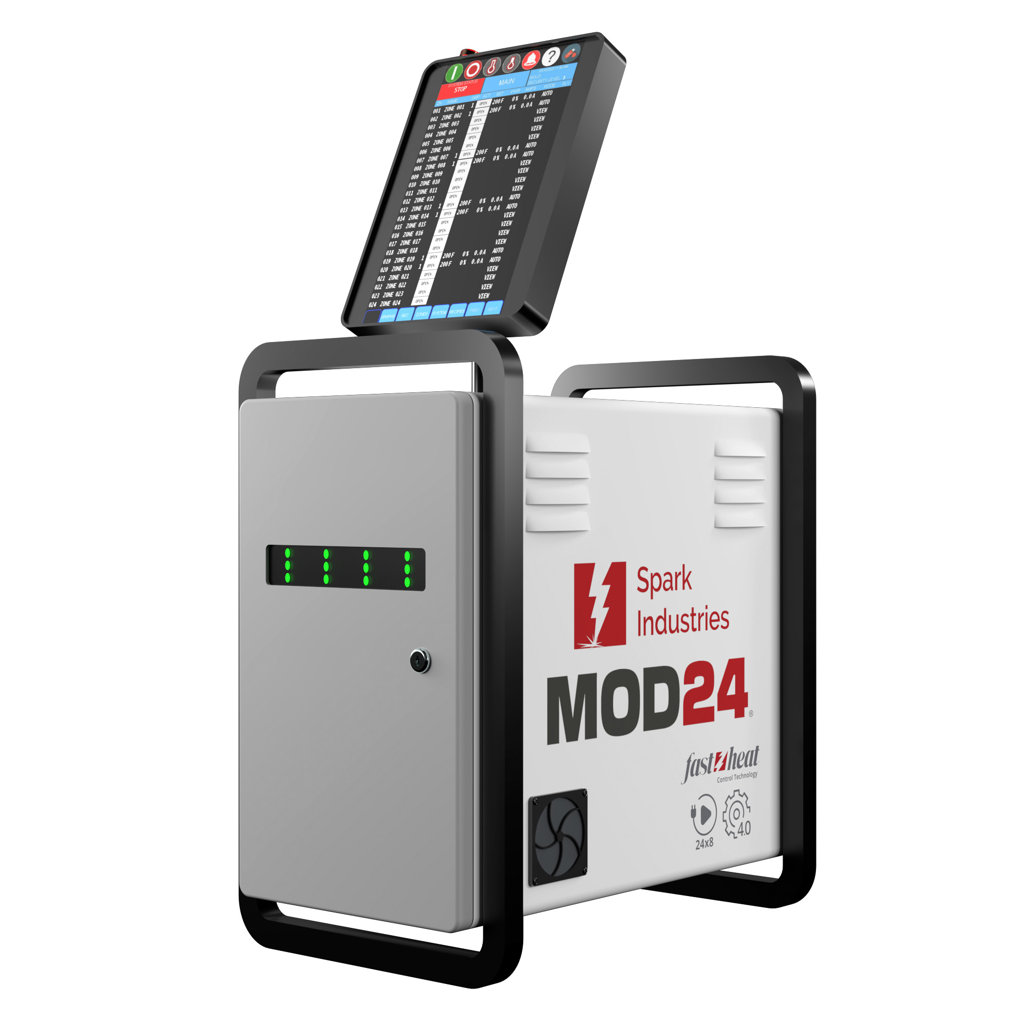
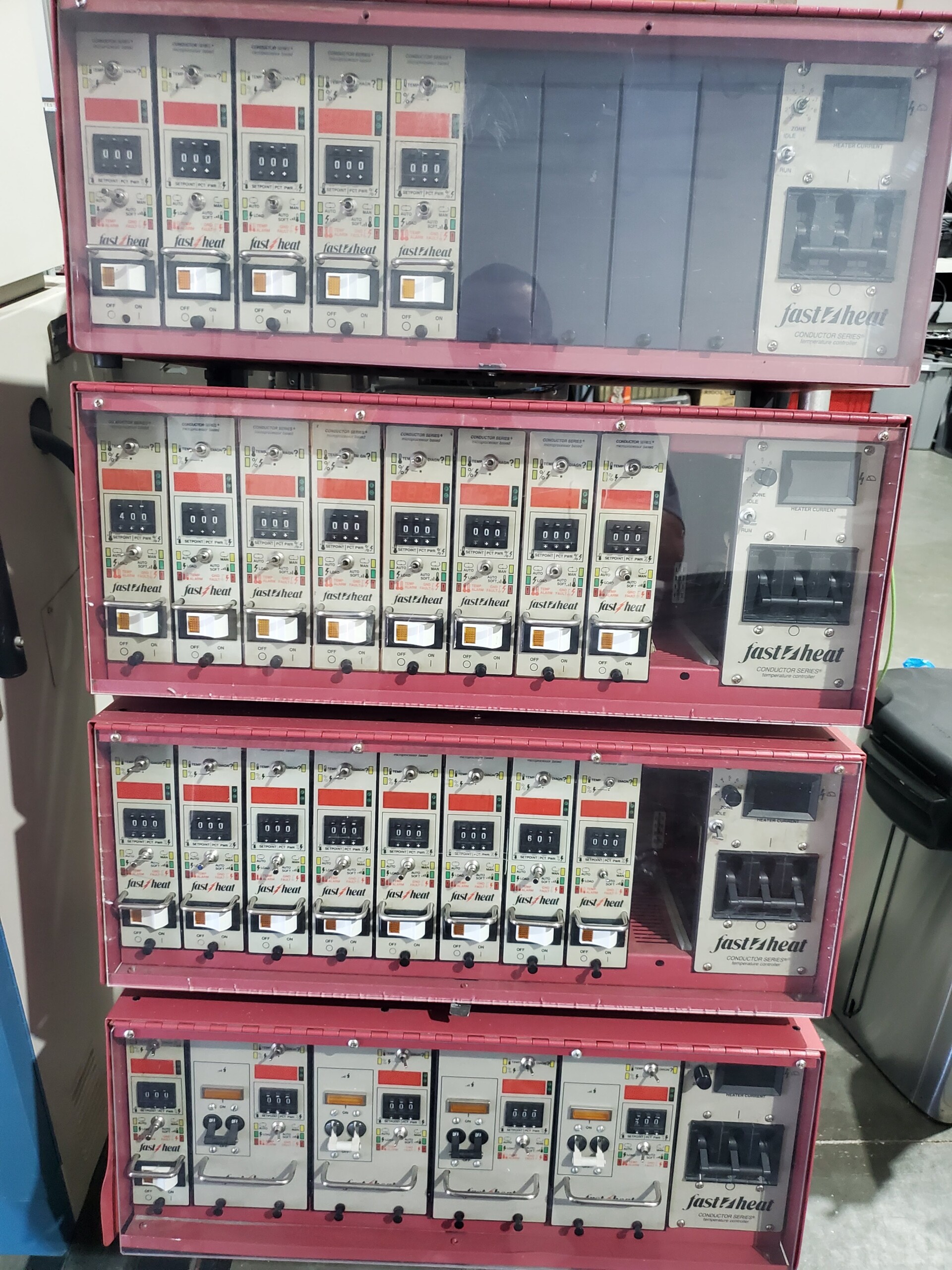
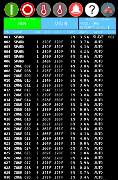 The Pulse hot runner controller has a 30-zone tabular view. It shows customizable zone names, tooling groups, actual temps, setpoint temps, % power, amps, mode (auto, manual, off, slave, and view), and slave assignment. Seeing these values on one screen instead of the old “Din-Controller” setup lets you know what’s happening with a tool from one screen.
After turning on the controller, select a recipe or set up a new recipe. Before hitting RUN, observe the actual temps from either Auto or View mode, and you’ll see if the closed loop thermocouple readings make sense or if you get any TC ALARMS or a TRIAC SHORT ALARM.
From here, select RUN (just one screen away; you can turn on Bake-Out, Evensoak™, and Soft Soak for cold starts). You can see high-amp zones (likely manifold or bridge zones) and low-amp zones (nozzles) during ramp-up. You’ll also quickly scan % power across the zones and be able to identify any abnormalities (improper temperature settings on the sprue or manifold, a zone that is 100% power but raises the temperature of a different zone, improper melt temp/plasticizing from the injection unit, water temperature on the mold is too cold, etc). The controller will alarm if there is an OPEN HEATER or OVER/UNDER AMP condition.
Once setpoints have been achieved, OVER/UNDER TEMP and OVER/UNDER % POWER are monitored.
References:
- kW Demand – We’ll show you how and why you should reduce kW demand.
- Maintenance – This covers preventative maintenance of hot runner systems, cables, and controllers.
- Processing – What’s happening behind the scenes in your hot runner system, and why does it matter for processing (better cavity-to-cavity balance, lower operating temperatures)?
- Molding Cell Integration – How could communications between your hot runner controller, the injection molding machine, or other auxiliaries optimize your molding cell?